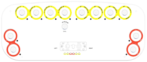
MIMO 8 has industry leading gains achieved through innovated larger radiator design and cable elimination technology.
8-Port MIMO
High Gain
Low PIM
Dual-Band
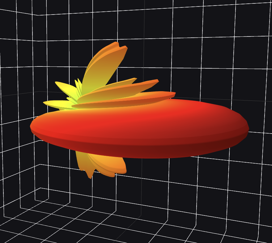
Antenna Gain
$$G = \frac{4\pi A_e}{\lambda^2} = \frac{4\pi}{\lambda^2} \cdot \eta \cdot A_{physical}$$
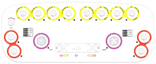
Radiator Array
Phase Shifter
CABLE
ELIMINATION LAYER